
Microwave Electronics
Last semester given: 2021-2022 Spring
Textbook: D. Pozar “Microwave Engineering” 4. Edition, Wiley
There are five bi-weekly homework assignments.
Moodle is used as a tool to provide communication among students and also with the instructor.
AWR is used as the CAD tool of the course.
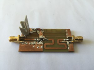
In Spring 2016, the students designed and fabricated RF amplifiers using a discrete transistor in the 360MHz to 2.1GHz range similar to the one shown in the figure. PCB boards were designed using AWR layout tool. Students measured the S-parameters, noise figure, P1dB, and P3rd of the amplifier they built. They learned to use a network analyzer, a noise figure meter, and a spectrum analyzer. In the final stage of the project, the amplifiers designed by different students were combined to form a single-conversion transmitter and a single-conversion receiver.
In the Spring of 2018, the project was about designing a low-noise or high-gain amplifier using a BJT (BFU520W). Each student had a different frequency range (450MHz to 1450MHz) with 10% bandwidth. The students designed the PCB using the AWR layout tool after designing the amplifier using the same tool. Students measured the S-parameters, noise figure, P1dB and P3rd of the amplifier they built.
Subjects covered:
- High-frequency effects, lumped/distributed elements
- Transmission lines, microstrips
- Smith Chart, use of CAD tools
- S-parameters, signal flow modeling
- Matching circuits
- Power gain equations
- Amplifier stability, stability circles
- Constant gain circles
- Noise, noise figure and noise temperature
- Noise in transistors and amplifiers, constant noise figure circles
- Noise in amplifiers and constant noise figure circles
- Bias circuits, wide band amplifiers, balanced amplifiers
- Detectors, mixers
- PIN switches, attenuators